
A fixed gas detection system is only as dependable as the connection between its field detectors and the control panel. In practice, most installation problems traced back after commissioning have little to do with the sensors themselves and a great deal to do with gas detector controller wiring: undersized cables, missing shields, floating grounds or misread terminal diagrams. This article walks through how 4-20mA current loops work in a typical fixed gas detection installation, how detectors are connected to a multi-channel controller, and which checks help a project team avoid the most common wiring faults before a system goes live.
Why the 4-20mA Current Loop Remains the Industry Standard
The 4-20mA analog current loop has been the default signal standard for industrial transmitters for decades, and fixed gas detectors are no exception. The detector regulates the current flowing in the loop so that 4mA represents the zero point of the measuring range and 20mA represents full scale. A reading halfway up the range is transmitted as 12mA, and the controller converts the received current back into a gas concentration for display and alarm processing.
Current signals have two practical advantages over voltage signals. First, current is essentially immune to voltage drop along the cable, so the reading at the controller stays accurate even over long runs. Second, the “live zero” at 4mA makes fault detection straightforward: if the loop current falls to 0mA, the controller knows the cable is broken or the detector has lost power, rather than assuming the gas concentration is simply zero. Many detectors also use defined current levels below 4mA, such as around 2mA, to signal an internal fault or a sensor in maintenance mode. Digital alternatives such as RS485 Modbus are increasingly common for large systems, but for small and mid-sized installations the 4-20mA loop is still the configuration most engineers specify first.
Two-Wire, Three-Wire and Four-Wire Detector Connections
Before pulling any cable, confirm which connection scheme the detector uses, because the three common schemes are wired differently:
- Two-wire detectors draw their operating power from the signal loop itself. The same pair of conductors carries both the 24V DC supply and the 4-20mA signal. This scheme suits low-power sensing technologies and keeps cabling simple, but the detector must be able to operate on less than 4mA of standing current.
- Three-wire detectors use one conductor for the positive supply, one for the 4-20mA signal output and one shared common. This is the most widespread arrangement for fixed gas detectors, including catalytic and infrared combustible gas detectors whose sensors need more power than a two-wire loop can deliver.
- Four-wire detectors separate the power supply pair from the signal pair completely, which can be considered where the detector is powered locally or where the design calls for galvanic separation between power and signal circuits.
Mixing these schemes up is one of the most frequent causes of dead channels at commissioning. Always wire from the manufacturer’s terminal diagram for the specific model, not from a generic drawing, and label both ends of every conductor.
Cable Selection, Distance and Loop Resistance
For 4-20mA gas detector circuits, shielded twisted-pair or three-core shielded cable is the usual choice. The shield helps protect the low-level signal from interference produced by motors, variable frequency drives and power cabling. As a general rule, the shield should be earthed at one end only, normally at the controller, to avoid ground loops; route signal cables in separate trays or maintain spacing from power cables where the site layout allows.
Cable cross-section is driven by two limits: the voltage available at the detector and the total loop resistance the transmitter can drive. Every meter of conductor adds resistance, and the supply voltage at the far end must stay within the detector’s specified operating window after the drop across the cable. On long runs, moving from 0.75mm2 to 1.5mm2 conductors, or raising the supply within the permitted range, is often the difference between a stable channel and one that drops out when the sensor draws peak current. Loop calculations should be checked during design rather than discovered as a problem on site.
Connecting Multiple Detectors to a Multi-Channel Controller
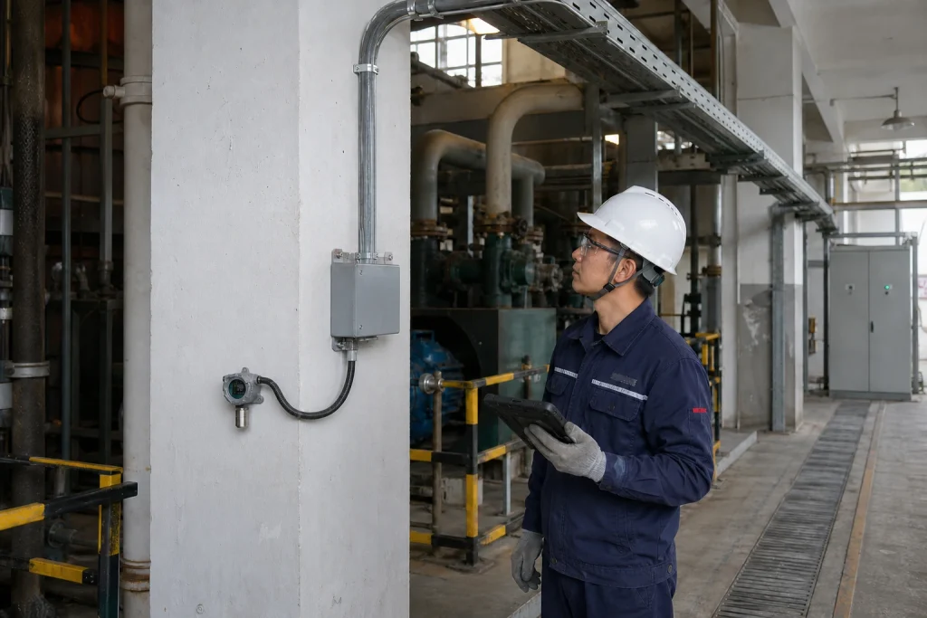
In a typical plant installation, each detector is wired back to its own channel on a gas detection controller installed in a control room or electrical room, that is, in a non-hazardous (safe) area away from the monitored process. Star wiring, with a dedicated home-run cable per detector, is the standard topology for analog loops; unlike a digital bus, 4-20mA channels are not daisy-chained.
Group channels logically during design. Assigning detectors to channels by area or by gas type makes alarm response faster and simplifies maintenance, for example keeping the combustible gas detectors for a boiler room on consecutive channels, with toxic gas points grouped separately. The controller side of the system also includes relay outputs for beacons, sounders and ventilation interlocks, so wiring planning should cover those output circuits, plus battery-backed power where the safety concept requires the system to ride through mains failures. An overview of typical panel options is available on our gas alarm controllers page.
Commissioning Checks Before Handover
A structured loop check turns wiring theory into a working system. The following sequence is commonly used:
- Verify supply voltage at each detector terminal under load, not just at the panel.
- Confirm each channel reads a stable 4mA baseline in clean air after the sensor has warmed up and been zeroed.
- Apply test gas or use the detector’s signal simulation function to drive the loop toward 20mA and confirm the controller displays the expected concentration on the correct channel.
- Trip each alarm level and confirm the intended relays, sounders and interlocks respond.
- Disconnect one conductor per channel briefly to confirm the controller reports a loop fault rather than a healthy zero reading.
- Record channel mapping, cable IDs and as-left settings in the commissioning file for future maintenance and calibration work.
Sites with documented loop-check records consistently spend less time diagnosing faults later, because a technician can trace any channel from sensor to relay in minutes.
Why ASA
ASA supplies fixed gas detectors, dust monitors and gas alarm controllers to industrial buyers across Europe and the Middle East. Our product line covers oxygen, toxic and combustible gas points together with multi-channel controllers, so a complete detection loop can be sourced and supported by one engineering team. We assist with channel planning, wiring questions and documentation during your project, and our sales engineers respond quickly to technical queries. To discuss a gas detection project or request a quotation, contact the ASA team.
Disclaimer: Product availability, specifications, measuring ranges, alarm configurations and certification coverage vary by model and region. The information in this article is provided for general reference only and does not constitute a performance guarantee, safety assurance or compliance statement. Always refer to the official product documentation and confirm suitability, certification status and local regulatory requirements with our team before selection, installation or use.