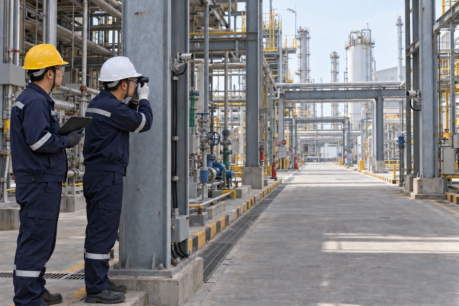
For industrial buyers, sil gas detection is a question about the complete protective function, from sensing a hazardous condition to carrying out the required action. A request for “SIL 2” needs more definition than a detector model and an alarm threshold. Procurement teams in Europe and the Middle East should establish what action the system must perform, which equipment is included, and what evidence supports the intended use. This helps turn a broad tender requirement into a specification that suppliers and project engineers can evaluate.
What SIL 2 Actually Describes
SIL means Safety Integrity Level. It expresses the required integrity of a defined safety function. SIL 2 is one of four levels in the IEC 61508 framework. The target comes from risk assessment, including the protection already provided by other measures. It is not a measurement accuracy grade or a universal rating for an entire facility.
For a low demand safety function, the SIL 2 quantitative band corresponds to an average probability of dangerous failure on demand of at least 0.001 and less than 0.01. Its reciprocal gives a theoretical risk reduction factor greater than 100 and up to 1,000, subject to the assessment assumptions. High demand and continuous operation use a different failure measure. These figures describe the specified function under defined conditions, not the percentage of gas releases a detector will discover. Meeting a numerical band alone is also insufficient: systematic failures and architectural constraints matter. The IEC functional safety overview explains the relationship between safety functions, integrity and risk reduction.
Define the Function Before Selecting Equipment
Start the purchasing brief with a clear description of the hazard and the required response. A hypothetical function might detect a hazardous gas condition in a defined area and initiate isolation through a specified shutdown path. The responsible engineer must establish the detection conditions, required action, allowable response time and safe state. An alarm that depends on an operator is a different arrangement and needs its own assessment of human response.
The complete path may include sensors, wiring, power supplies, input interfaces, logic, output circuits and final elements such as isolation valves. A component’s documented capability does not automatically demonstrate the integrity of that assembled path. HSE’s control systems guidance addresses protective systems, independence and operator involvement.
A useful tender attachment is a cause and effect schedule. For each initiating condition, identify the expected indication, alarm, automatic action, reset conditions and responsible equipment. Ask the project team to mark which actions are credited in the risk assessment. Keep general monitoring duties visible as well, so that a requirement for a safety function is not accidentally applied to every display or reporting channel.
Separate Detection Coverage from Functional Integrity
A working detector can only respond when the relevant gas reaches its sensing location in detectable conditions. Release position, ventilation, obstructions and the layout of equipment affect coverage. Sensor selection also needs to reflect the target gas and operating environment. Functional integrity and the likelihood of detecting a release therefore require separate attention.
HSE’s gas detection guidance highlights detector positioning, maintenance, calibration and performance testing. A strong equipment reliability claim cannot compensate for a layout that leaves important release scenarios undetected. Likewise, adding detectors without evaluating their locations and shared vulnerabilities does not establish the required protection.
For procurement, request a documented basis for the proposed detector layout. Ask which release scenarios it addresses and which assumptions depend on ventilation or process conditions. The project reviewer should be able to trace each assumption to an agreed input. If the plant layout changes, flag the detection arrangement for review instead of treating the original equipment quantity as a permanent design requirement.
Review Evidence and Plan the Operating Life
Functional safety continues through implementation, operation and maintenance. The 61508 Association’s explanation of IEC 61508 describes this lifecycle approach. For process industry applications, IEC 61511 provides the sector framework; applicability should be established by the responsible project specialists.
When a supplier makes a functional safety claim, request the supporting assessment and safety manual for the exact equipment configuration. Check model identity, hardware and software revisions, permitted architecture, operating restrictions and maintenance assumptions. Have the responsible engineer determine whether this evidence supports the intended role. A general brochure statement is not enough to resolve those questions.
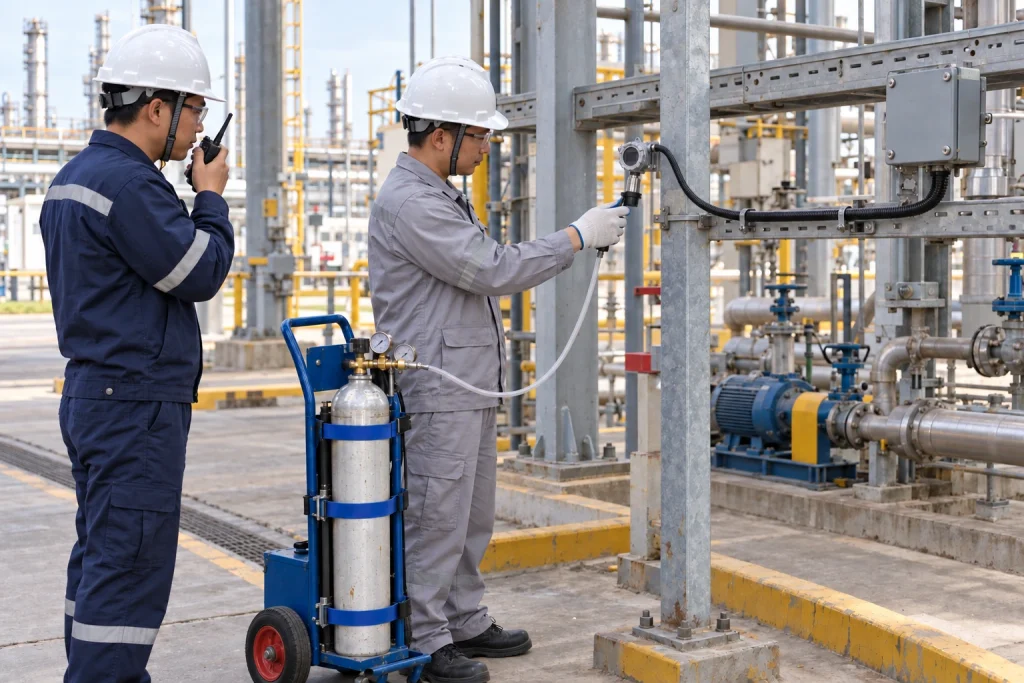
Calibration and proof testing have different purposes. Calibration checks measurement against a reference; proof testing seeks dangerous failures that may otherwise remain hidden. The procedure and interval must follow the verified design assumptions and applicable documentation. A successful local gas response test alone does not show that a downstream valve will perform the required action.
Before placing an order, agree who will provide and approve:
- The safety requirements specification and the boundary of each credited function.
- Equipment documentation and the assumptions used in system verification.
- Commissioning procedures, acceptance records and arrangements for resolving deviations.
- Proof test instructions, maintenance responsibilities and controls for bypasses or changes.
Assigning these deliverables makes quotations easier to compare. It also exposes gaps that could otherwise appear during commissioning, when replacing equipment or revising the shutdown arrangement may be disruptive.
Why ASA
ASA’s product lines cover gas detectors, dust alarm equipment and gas alarm controllers. Buyers developing a monitoring specification can review the gas detector range and discuss the application with the team. Selection should remain tied to documented model capabilities and project requirements.
For a focused engineering discussion, provide the target gas, site conditions, proposed control arrangement and any functional safety requirements in the inquiry. Request the relevant documentation and identify unresolved suitability questions before final selection. This article makes no SIL capability claim for ASA equipment. Contact ASA to discuss product selection and the information needed for your project review.
Disclaimer: Product availability, specifications, measuring ranges, alarm configurations and certification coverage vary by model and region. The information in this article is provided for general reference only and does not constitute a performance guarantee, safety assurance or compliance statement. Always refer to the official product documentation and confirm suitability, certification status and local regulatory requirements with our team before selection, installation or use.