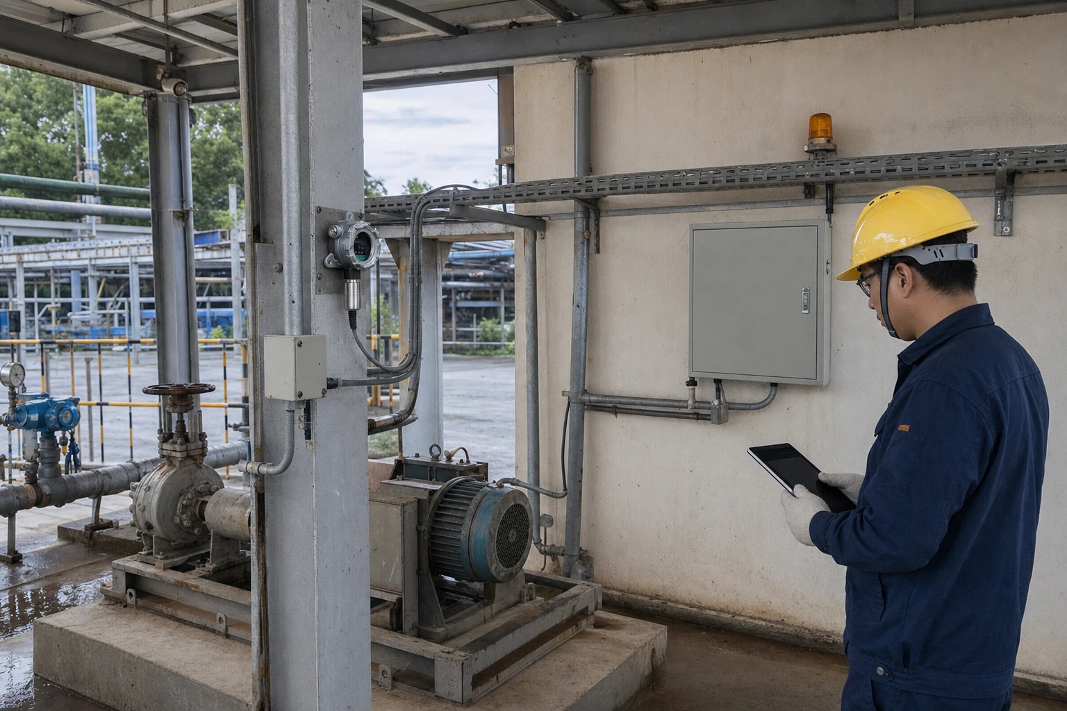
Selecting the right signal output is one of the most consequential decisions when specifying a fixed gas detection system, because it determines how measurement data travels from the sensor head to the control room. A 4-20mA gas detector transmits its reading as a continuous analog current loop, while an RS485-equipped detector communicates digitally, typically using the Modbus RTU protocol. Both approaches are well established in industrial safety engineering, and both can be considered for new installations as well as retrofits. This guide explains how each output works, where each one tends to fit best, and what wiring, distance and integration factors procurement and engineering teams should weigh before committing to one architecture.
How the 4-20mA Current Loop Works
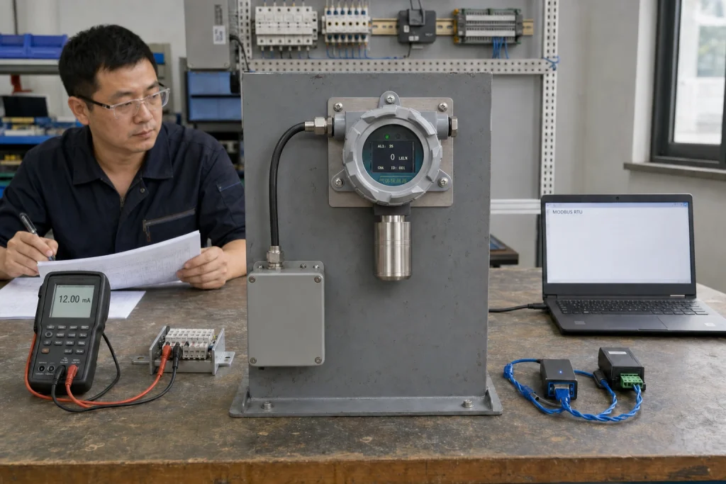
The 4-20mA current loop is one of the oldest and most widely used signalling standards in process instrumentation. The detector scales its measurement across a current range: 4mA usually represents the zero point of the measuring range, and 20mA represents full scale. A reading halfway up the range is transmitted as 12mA, and the receiving controller or PLC converts the current back into a concentration value.
Using current rather than voltage brings a practical advantage: current is not degraded by ordinary voltage drop along the cable, so the signal remains usable over long runs when the loop is properly engineered. The live zero at 4mA also provides inherent fault indication. If the loop reads 0mA, the controller knows the cable is broken or the transmitter has lost power, rather than assuming the gas concentration is simply zero. Many transmitters additionally use currents below 4mA or above 20mA to flag fault or over-range conditions, although the exact convention varies by manufacturer and model.
Wiring is straightforward. Depending on the transmitter design, a loop may use two, three or four conductors, and each detector typically has a dedicated home-run cable back to the controller input. This point-to-point topology is simple to commission and troubleshoot: one channel, one cable, one device.
How RS485 Digital Communication Works
RS485 is a differential serial communication standard designed for noisy industrial environments and multi-device networks. Rather than encoding the measurement as a current level, the detector transmits data digitally, and in gas detection this is most commonly done with the Modbus RTU protocol. A master device, such as a gas alarm controller, PLC or SCADA gateway, polls each detector by address and receives its data in return.
The defining feature of RS485 is the bus topology. Multiple detectors can share a single twisted-pair cable, daisy-chained from device to device, with each unit assigned a unique address. This can significantly reduce cabling in installations with many measurement points spread across a site, since one trunk cable may replace dozens of individual home runs.
Digital communication also carries richer information. Where an analog loop conveys only one value, a Modbus register map may expose the concentration reading together with gas type, unit of measure, alarm status, fault codes and other diagnostic data. For plants building centralized monitoring or predictive maintenance programs, this additional context is often the deciding factor.
Comparing the Two: Wiring, Distance, Data and Reliability
Neither output is universally better; each has a profile of strengths that suits different projects.
Cabling effort. A 4-20mA architecture needs one cable per detector, which is manageable for a handful of points but grows quickly on larger sites. An RS485 bus can serve many detectors on shared cabling, which may reduce material and installation labor on distributed installations.
Simplicity and interoperability. The analog loop is essentially universal. Any controller or PLC with a standard analog input can read a 4-20mA gas detector without protocol configuration, register maps or address planning. RS485 integration requires matching baud rate, parity, addressing and register definitions between detector and master, so commissioning demands more configuration work and good documentation from the supplier.
Data depth. The analog signal carries a single continuously updated value, which is exactly what a safety readout needs. RS485 provides multi-parameter data and diagnostics, which supports asset management as well as safety monitoring.
Failure behavior. The 4-20mA live zero gives immediate, per-channel line fault detection. On an RS485 bus, the master detects a failed device through communication timeouts, but a physical fault on the shared trunk can affect several devices at once, so bus segmentation and wiring quality deserve attention at the design stage.
Noise immunity. Both methods are designed for industrial environments. Current loops are robust against voltage drop and moderate interference, while the differential signalling of RS485 is specifically intended to reject common-mode noise on twisted-pair cable. In either case, shielded cable, correct grounding and separation from power conductors remain good engineering practice.
Choosing the Right Output for Your Application
A practical way to decide is to look at the receiving end first. If the detectors will land on a conventional gas alarm controller with analog input channels, 4-20mA keeps the system simple and vendor-neutral. If the readings feed a PLC, DCS or SCADA platform that already speaks Modbus, RS485 may integrate more naturally and deliver more usable data.
Project scale matters as well. Small installations with a few measurement points are commonly served by analog loops, while sites with many points spread over long distances often favor a bus architecture to control cabling costs. Some projects deliberately combine both: analog outputs for the core safety function and digital communication for supervisory monitoring. Many modern fixed gas detectors are available with both 4-20mA and RS485 outputs on the same transmitter, which preserves flexibility if the control architecture evolves later.
Finally, consider lifecycle factors. Maintenance teams familiar with loop checking and milliamp calibration may prefer analog systems, whereas teams managing large device fleets often value the remote diagnostics that digital communication can provide. Whichever direction you take, confirm the electrical details, supported protocol functions and register documentation with the supplier for the specific model under consideration.
Why ASA
ASA supplies a broad line of fixed gas detectors, dust monitoring instruments and gas alarm controllers for industrial customers across Europe and the Middle East. Our detectors are offered with the common industrial output options, and our engineering team can help you plan channel counts, bus layouts and controller pairing so the signal architecture fits your site rather than the other way around. We respond quickly to technical enquiries, provide integration documentation for our products, and support customers from specification through commissioning. To discuss the right output configuration for your project, contact the ASA team for a consultation.
Disclaimer: Product availability, specifications, measuring ranges, alarm configurations and certification coverage vary by model and region. The information in this article is provided for general reference only and does not constitute a performance guarantee, safety assurance or compliance statement. Always refer to the official product documentation and confirm suitability, certification status and local regulatory requirements with our team before selection, installation or use.