Specifying a complete gas detection system involves more than picking a sensor for each gas. A fixed installation that protects an industrial site is a chain of components: detectors in the field, a controller that gathers their signals, and alarm devices that turn a measurement into an action people can respond to. When any link in that chain is undersized or poorly matched, the whole system underperforms. This guide walks through the main building blocks, how they connect, and the questions procurement and engineering teams commonly work through when putting a system together for plants in Europe and the Middle East.
The Three Layers of a Fixed Gas Detection System
Most fixed installations can be described in three layers.
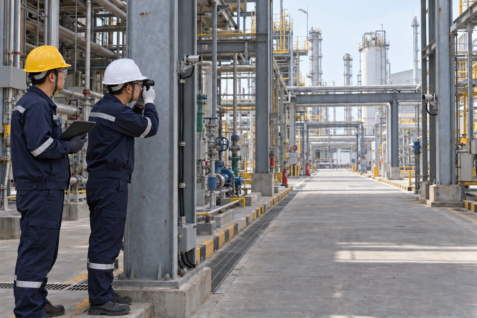
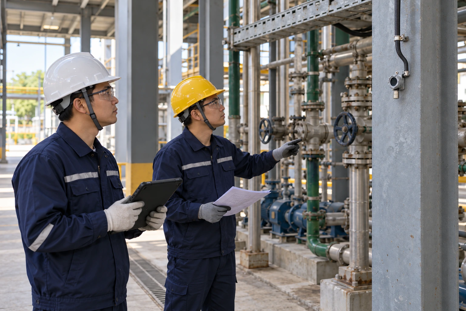
The sensing layer consists of fixed gas detectors mounted at points where a leak or accumulation is most likely to be detected. Each detector continuously measures one target gas, for example combustible gas as a percentage of the lower explosive limit (LEL), a toxic gas such as CO or H2S in ppm, or oxygen in percent volume.
The control layer is the gas alarm controller, usually installed in a control room or another non-hazardous area. It powers the detectors, reads their signals, compares readings against alarm setpoints, and drives outputs.
The alarm and action layer includes audible and visual alarms such as sounders and beacons, plus relay-driven actions like starting ventilation fans, closing solenoid valves, or signaling a plant control system. This layer is what converts a rising gas reading into a protective response.
Thinking in layers helps during specification because each layer has its own selection criteria, and the interfaces between layers, typically 4-20mA analog loops or RS485 digital communication, need to be defined early.
Choosing Detectors for Each Hazard
Detector selection starts with a simple inventory: which gases are present, where could they be released, and what concentration range matters. A boiler room with natural gas piping calls for combustible gas detection scaled in %LEL, while a wastewater pump station may need H2S monitoring in ppm, and a nitrogen-inerted storage area may call for oxygen deficiency monitoring.
Sensor technology follows from the gas. Catalytic bead and infrared sensors are commonly used for combustible gases, electrochemical cells for toxic gases and oxygen, and photoionization detectors (PID) for volatile organic compounds. Each technology has its own calibration needs, expected sensor life, and cross-sensitivity behavior, so it is worth confirming these details with the supplier for your specific gas mix.
Mounting height depends on gas density. Lighter-than-air gases such as methane accumulate high, so detectors like a methane CH4 gas alarm detector are typically mounted near the ceiling above potential leak sources, while heavier-than-air gases and vapors call for low-level mounting. For classified hazardous areas, the detector housing must carry an appropriate explosion protection rating for the zone; ASA detectors including the AN-O2-D, AN-CO2-D, AN-NH3-D, AN-CO-D, AN-VOC-D and AN-LEL-D carry China Ex Certificate EETI24.0463X (Ex db IIC T6 Gb, IP65), valid to Jan 2030. A broader overview of available fixed detector types is on our gas alarm detectors product center.
The Controller: Where Signals Become Decisions
The gas alarm controller is the hub of the system. Its core jobs are to supply power to field detectors, display live readings channel by channel, evaluate alarm thresholds, and operate output relays when a threshold is crossed.
Channel count is the first sizing decision. Count every detector point on the site plan, then add spare capacity for future expansion; retrofitting a larger controller later is far more disruptive than specifying spare channels up front. Multi-channel controllers such as the AN-3100H gas detection controller allow many detectors of different gas types to be monitored from one panel, which simplifies wiring, operator training, and maintenance. The controller itself is intended for installation in non-hazardous (safe) areas, typically a control room, with cable runs out to the detectors in the field.
Alarm logic deserves attention during specification. Most systems use at least two alarm levels per channel: a low-level warning that may trigger ventilation or alert operators, and a high-level alarm that drives evacuation signals or shutdown actions. Setpoints should be agreed with the site safety team and documented, and the relay assignments, which relay does what, at which level, on which channels, should be written into the commissioning plan.
Alarm Devices, Outputs and System Integration
Audible and visual alarm devices close the loop between measurement and human response. Sounders should be audible above local background noise, and beacons should be visible from normal work positions; in high-noise plants, combined sounder-beacon units at multiple locations are commonly used rather than a single device.
Beyond local alarms, most industrial projects need the gas system to talk to other systems. Typical integration paths include relay contacts wired to ventilation starters or shutdown circuits, 4-20mA retransmission of selected channels to a PLC or DCS, and RS485 communication for centralized monitoring. Defining these interfaces early avoids late-stage surprises in panel design and cabling.
Power integrity matters as well. A gas detection system is a safety function, so backup power provisions, such as supplying the controller from a UPS or a supervised power circuit, can be considered so that monitoring continues during a mains interruption.
From Design to Commissioning
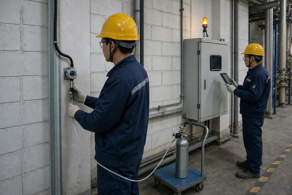
A workable delivery sequence looks like this. First, complete a hazard inventory and mark detector locations on the site layout, taking gas density, air movement, and likely leak points into account. Second, produce a cable and interface schedule covering detector loops, alarm devices, and integration signals. Third, install and wire the equipment, keeping analog signal cables separated from power cabling where practical. Finally, commission the system: verify each channel end to end, apply test gas to confirm detector response, check every alarm level and relay action, and record the results.
After handover, the system needs a maintenance routine. Periodic bump testing and calibration keep readings trustworthy, and sensor replacement intervals should follow the manufacturer’s guidance for each sensor type. A system that is designed well but never maintained will quietly lose the protection it was bought to provide.
Why ASA
ASA supplies a coherent product line for building complete systems: fixed detectors for combustible, toxic, VOC, oxygen and CO2 monitoring, dust alarm detectors, and multi-channel gas alarm controllers, all designed to work together over standard 4-20mA and RS485 interfaces. Our engineering team supports customers from detector selection and channel planning through to commissioning advice, with responsive communication for projects across Europe and the Middle East. If you are planning a new installation or extending an existing one, contact our team to discuss your site requirements and get a tailored configuration proposal.
Disclaimer: Product availability, specifications, measuring ranges, alarm configurations and certification coverage vary by model and region. The information in this article is provided for general reference only and does not constitute a performance guarantee, safety assurance or compliance statement. Always refer to the official product documentation and confirm suitability, certification status and local regulatory requirements with our team before selection, installation or use.