
Investigating gas detector false alarms requires a clear distinction between a genuine gas event, a changing sensor baseline and an instrument fault. An unexpected alarm is not evidence that the detector is wrong. For industrial facilities, the first priority is to follow the site emergency procedure and establish whether a hazardous atmosphere may be present. Once the area has been assessed by authorized personnel, a structured investigation can help maintenance teams identify the cause without weakening the protection the system was designed to provide.
Start with the event, not the reset button
Record the time, affected channel, displayed concentration, alarm state and any diagnostic message before clearing a latched indication. Note whether other detectors responded and whether the event coincided with cleaning, maintenance, a process change or a ventilation interruption. A brief release may have dispersed before someone arrives, so a normal reading later does not prove the original alarm was false.
Use the site’s approved assessment method, which may include an independent, appropriately selected and function-checked instrument operated by trained personnel. Do not enter a potentially hazardous area solely to inspect a detector. Any maintenance bypass or isolation should follow the site’s authorization process, with suitable temporary protection and a documented restoration step.
Compare the local detector indication with the controller or supervisory display. If both show the same changing concentration, investigate the atmosphere and sensing element. If the local reading is stable while the remote channel alarms, review signal transmission, channel configuration and controller diagnostics. This comparison helps locate the problem without assuming that every unwanted alarm originates in the sensor.
Understand zero drift before adjusting the baseline
Zero drift describes a change in the baseline under the reference conditions specified for the instrument. Possible contributors include sensor aging, contamination, environmental changes or an incorrect previous zero adjustment. A negative reading also deserves investigation: accepting a contaminated atmosphere as the reference can cause subsequent measurements to understate exposure.
Zeroing must follow the exact model’s instructions, including the required reference gas and stabilization conditions. Do not assume that outdoor air or an apparently empty room is a valid reference. Oxygen channels and other measurement technologies may require different procedures. Industrial Scientific explains the risk of misleading results from drift or an incorrect zero in its guidance on negative gas readings.
Before making an adjustment, record the original reading and check the service history. Look for repeated corrections, recent sensor replacement and changes in operating conditions. Repeatedly zeroing a drifting sensor can conceal deterioration rather than resolve it. If the baseline remains unstable after the approved procedure, consult the manufacturer about further diagnostics or replacement.
Keep zero adjustment separate from sensitivity verification. A detector can display the expected baseline yet respond incorrectly to gas. Use the specified calibration procedure and approved gas delivery accessories to evaluate the complete measurement response.
Read fault codes in the correct manual
Fault codes are specific to the instrument, its configuration and sometimes its firmware. The same number or abbreviation can mean different things on different detectors. Record the complete code, model identification and relevant operating state, then consult the corresponding manual. Avoid using an unrelated online fault table as a repair instruction.
Depending on the design, diagnostics may identify a sensor connection problem, a supply issue, a communication interruption or a calibration failure. Qualified personnel should check the indicated subsystem using the manufacturer’s procedure. Opening equipment, disconnecting sensors or making electrical measurements requires appropriate site authorization and environmental precautions.
A fault indication does not necessarily represent a measured gas concentration, but it may mean that monitoring is impaired. Confirm how the receiving system distinguishes gas alarms from instrument faults. Where a detector communicates with a controller, review channel mapping and compatible signal settings at both ends. Teams comparing system architectures can review ASA’s gas alarm controller category as a starting point for a documented compatibility discussion.
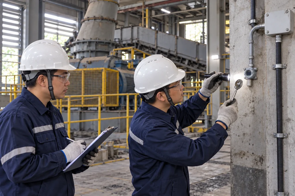
Investigate recurring alarms and verify the repair
Recurring events should be compared against operating conditions rather than dismissed as nuisance behavior. Cleaning chemicals, process vapors or nearby activities may affect some sensor technologies. Cross-sensitivity depends on the sensing element and the interfering substance, so consult the relevant manufacturer data before attributing a response to interference.
Inspect accessible sampling paths, filters and protective accessories under the approved maintenance procedure. Obstructions, moisture or damaged tubing can affect sample delivery in systems that use these components. For electrical or communication problems, qualified technicians can review power quality, connections and installation practices against the equipment documentation.
Do not raise alarm thresholds simply to silence repeated events. Alarm settings belong to the site’s risk assessment and operating procedures. A setting change requires a technical justification and the appropriate approval, especially where the output initiates ventilation, shutdown or another protective action.
After corrective work, perform the checks required by the manufacturer and site procedure. A bump test checks response and alarm operation; calibration evaluates and adjusts measurement response against a reference. Industrial Scientific describes this distinction in its calibration and bump testing guidance. Neither a cleared fault nor a successful display reset alone demonstrates restored performance. Verify the relevant signal path and alarm functions through an authorized test, then document results and remove approved bypasses.
Why ASA
ASA’s product scope includes gas detectors, dust alarm detectors and gas alarm controllers, providing a practical starting point for industrial monitoring discussions. Selection should connect the target hazard, installation conditions and required alarm functions with the documentation for the proposed equipment. No single troubleshooting procedure applies to every sensor or installation.
For an engineering support inquiry, prepare the detector model, diagnostic message, event history, calibration records and controller details. This information helps focus the discussion on the affected measurement or signal path. Contact ASA to discuss your monitoring requirements and request the documentation needed to evaluate equipment suitability and maintenance arrangements.
Disclaimer: Product availability, specifications, measuring ranges, alarm configurations and certification coverage vary by model and region. The information in this article is provided for general reference only and does not constitute a performance guarantee, safety assurance or compliance statement. Always refer to the official product documentation and confirm suitability, certification status and local regulatory requirements with our team before selection, installation or use.