
For industrial buyers specifying fixed VOC monitoring, understanding pid correction factors is essential to interpreting readings after calibration with isobutylene. A displayed concentration needs a clear basis: which gas was used for calibration, which substance the instrument is configured to report, and whether the process atmosphere matches that assumption. Procurement teams should establish these details before comparing detector proposals or agreeing an alarm strategy. This guide explains the measurement principles and the documentation that supports a practical calibration plan.
Why Isobutylene Is Used for PID Calibration
A photoionization detector uses ultraviolet light to detect compounds that can be ionized by its lamp. Different compounds produce different responses. Isobutylene is commonly used as a reference gas, allowing suitable instruments to be calibrated against one standard before applying a compound-specific correction. A reading expressed as isobutylene equivalents therefore does not automatically represent the concentration of another solvent. Honeywell’s PID instrument response guidance explains this distinction and the use of correction factors.
For a purchasing specification, separate the calibration gas from the target gas. Identify the process substances by chemical name and, where available, CAS number. Ask the supplier to confirm whether the proposed detector can measure those substances with its specified lamp and configuration. A broad description such as solvent vapor is not sufficient to establish a defensible concentration basis.
Also define the purpose of the installation. Leak indication, process trend monitoring and exposure assessment raise different questions about instrument selection and interpretation. A fixed detector may be evaluated as part of a monitoring system, but its reading alone does not establish personal exposure or confirm that an area is safe to enter.
How to Apply a Correction Factor Without Double Counting
Under the multiplication convention described in the Honeywell guidance, the estimated target concentration equals the isobutylene-equivalent reading multiplied by the applicable correction factor. Some instruments apply the selected factor internally and display the target concentration directly. Applying the factor again to that corrected display would produce an incorrect result. Verify the calculation convention in the detector’s own manual before configuring software or controller scaling.
The factor must match the target substance, installed lamp and instrument documentation. MSA’s PID theory and definitions emphasizes matching the lamp, response factor and alarm settings. These manufacturer references explain general principles; their settings should not be transferred to an ASA detector without model-specific confirmation.
Record the calculation location explicitly. The detector display, transmitted measurement and receiving system should have a documented concentration basis. During commissioning, compare the local reading with the value shown at the operator interface using the approved test procedure. This helps identify configuration discrepancies before operators depend on the displayed value.
Do not select an alarm threshold simply by copying a number from a correction-factor table. Ask the responsible safety specialist to establish the alarm strategy for the actual substances and operating conditions, then confirm that the complete measurement chain represents those decisions consistently.
Build a Repeatable Calibration and Verification Procedure
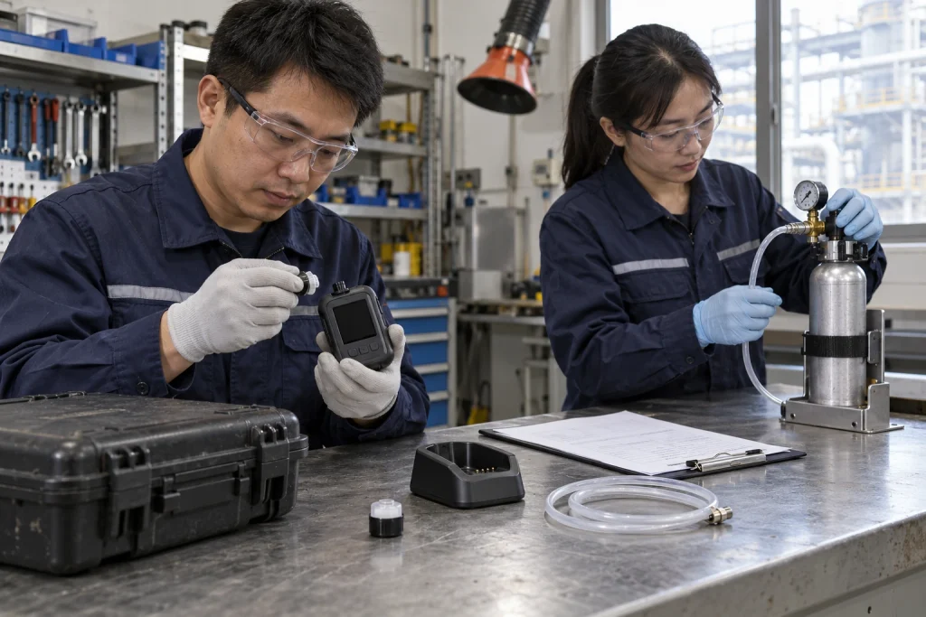
Use the detector manufacturer’s procedure for zeroing, span calibration and subsequent verification. The work instruction should identify the required gas, concentration, balance gas, delivery accessories and operating conditions. Do not assume that a cylinder or regulator used for another instrument is suitable. Check the cylinder label, expiry date and documentation before starting work.
For an operating installation, coordinate testing with the personnel responsible for alarms and connected equipment. Document any authorized temporary inhibition, the compensating measures required by the site and the steps for restoring normal operation. Calibration work should not leave an undocumented gap in monitoring or an alarm output unintentionally disabled.
- Record the detector identity, installed sensor configuration and current gas selection.
- Document the calibration gas identity, cylinder reference and procedure revision.
- Capture the initial condition and the result after adjustment or maintenance.
- Verify the relevant indication and alarm functions according to the approved site procedure.
- Record restoration to service, unresolved faults and the next scheduled review.
Keep a functional gas challenge distinct from a calibration adjustment. Specify what each activity is intended to verify and what constitutes an acceptable result. Set maintenance intervals using the manufacturer’s instructions and site experience, with review after process changes or abnormal readings. A calendar entry is useful only when the procedure and acceptance criteria are equally clear.
Recognize Mixture and Environmental Limitations
A conventional PID reading does not identify every chemical in an unknown mixture. Selecting one solvent’s factor does not make other responding vapors disappear. If the mixture changes during cleaning, transfer or production, a single-compound interpretation may no longer be appropriate. Document the expected composition and seek a suitable measurement approach where individual substances must be distinguished.
Environmental conditions also affect interpretation. Honeywell’s correction-factor measurement note identifies lamp and sensor design and humidity as influences on response. A factor determined under one set of conditions should not be treated as a guarantee for every installation.
Include process changes in the management plan. A replacement solvent, revised cleaning method or different material supplier should trigger a review of the target substance and configured factor. Retain earlier configuration records so that trends from different reporting bases are not compared as though they were identical.
Why ASA
ASA’s product offering covers gas detectors, dust alarms and gas alarm controllers. Buyers evaluating a PID VOC gas detector can bring the target substance list and installation requirements to the selection discussion. Ask our team to confirm the applicable documentation, calibration method and correction-factor handling for the proposed model.
For engineering coordination, send the process description, expected mixture, monitoring objective and maintenance requirements with your inquiry. These details support a focused technical review. Contact ASA to discuss your VOC monitoring requirements and confirm model suitability before procurement.
Disclaimer: Product availability, specifications, measuring ranges, alarm configurations and certification coverage vary by model and region. The information in this article is provided for general reference only and does not constitute a performance guarantee, safety assurance or compliance statement. Always refer to the official product documentation and confirm suitability, certification status and local regulatory requirements with our team before selection, installation or use.